Configuring CMC Selector Selector-Push Units involves setting up various parameters and options to ensure it operates according to your specific requirements. This process allows you to customize the push button unit’s functionality, enabling you to control motor speed, direction, and other critical aspects of motor operations. By properly configuring the CMC Selector Push Button Unit, you can optimize motor control, improve operational efficiency, and enhance safety measures within your industrial processes.
CMC selector-push units have hundreds of thousands of possible combinations, all with their own unique part number. 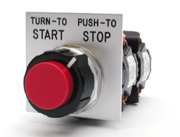 This page will walk you through how to find the part number of the unit you’re looking for. An example of a finished part number is 914AGA011BB. The part number can be split into 914-A-G-A-01-1-BB. The “914” is the operator knob color, the “A” is the selector action, the “G” is the cam code, the second “A” is the operator function, the “01” is the number of lamp terminals and types of lamps, the “1” is the cam orientation, and the “BB” is the push cam code.
Instructions
Step 1: Determine the knob color
If grey, the part number starts with 911
If black, the part number starts with 914
Step 2: Determine Selector Action
Identify the letter that matches up with positions needed and put that onto the part number.
Step 3: Determine Cam Code
Match your circuit requirements in one cam code column from the chart.
Develop the catalog listing of the unit, including the shaded area letters of the cam code configuration selected.
Consider position number 1 as the furthest counter-clockwise device position. Order contact block(s) and adapter kit as indicated in the left hand column of the cam code selection chart.
Step 4: Determine Operator Function
The letter representing the operator function will be A, B, C, D, or F.
A – Maintained
B- Clockwise spring return from left (2 and 3 position)
C- Counterclockwise spring return from right (2 and 3 position)
D- Clockwise and counterclockwise spring return to center from left and right (3 position)
F- Uni-rotational clockwise (4 position only, no stop)
Step 5: Determine Lamp Terminals and Service
Identify the numbers that match up with the number of terminals and type of lamp needed, and put that into the part number.
Step 6: Determine Cam Orientation
Insert the cam orientation code from the shaded area of the cam code chart. The area is labeled orientation and it must be from the same column as the cam.
Step 7: Determine Push Cam Code
Insert the push cam code from the shaded area of the cam code chart. The area is labeled push cam code and it must be from the same column as the cam.
Once you get through all 7 steps, you’ll have a complete part number. If you need a quote on your switch, or have a more complicated switch that doesn’t match up with any of our standard circuit configurations, be sure to contact us.